#6 input lut series#
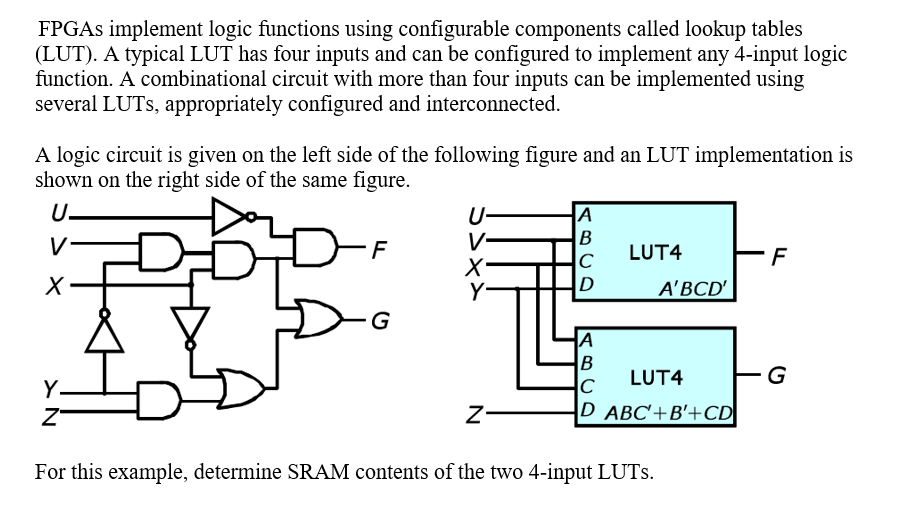
LUTs are commonly chained or combined in series to implement larger Boolean equations. Altera has had a structure that allows allocation of their LUT structure to give you various combinations of inputs for each of their two. Older families of Xilinx parts (with 4-input LUTs, Pre V5) didnt have two outputs. In older Virtex and Spartan technologies, even though the LUT was a 4-input LUT, Xilinx used the figure 1.25 logic cells per LUT/FF pair in the CLB. The innovative VirtexTM-5 architecture, which is based on a real 6-input LUT with dual-LUT capability, provides substantial resource utilization advantages. Having a 4-input LUT serving as an inverter isnt very efficient but its 4x less logic than the 6-input LUT as an inverter. (ALM) with 6 inputs, Quartus II uses 64-bit codes (eight-digit hexacodes). the actual number of LUT inputs (the newer Xilinx families all use 6 input LUTs) - additional combinatorial logic that exists in the FPGA fabric (outside the actual LUT). This characteristic is illustrated in the figure below. If Stratix IIGX FPGA is used that has the so-called adaptive logic modules. The vector of programming bits would be used.Ī LUT can implement any Boolean logic equation limited only by the number of inputs of the LUT’s size. But given 2-inputs, there’s lots of possible output combinations, which all must be possible to satisfy given a 2-input LUT. The above examples show a 2-input LUT that has been configured to be an AND gate and an OR gate. LUTs are commonly used to create and save color grades that can be applied to give your clips a unique style. A Look-Up Table (LUT) is how any arbitrary Boolean logic gets implemented inside your FPGA. You can use LUTs to manipulate saturation and contrast, or completely change the color of a clip.

The memory entries in blue boxes in part (b) of the figure above represent the configurable table entries under the ‘out’ column in part (a). It processes a color value and outputs a corresponding value. In this paper we present the use of 6-input LUT architecture for some Boolean functions (Mux8, Mux16, Mux32, Mu圆4, OP64, OR40 and AND40). The number of inputs of a LUT is calculated as the log base 2 of N. The example in the figure above is a LUT where N=8. LUTs are typically constructed using an N:1 multiplexer (shown in green in Figure 4b) and an Nx1-bit memory (shown in blue). (a) Truth table relationship of a LUT (b) Diagram of logical behaviour of a LUT ¶Īlthough mainstream FPGAs typically use 6-input LUTs, this example illustrates a 3-input LUT for simplicity but the principle of operation is the same.


 0 kommentar(er)
